
- +8615586668226
- [email protected]
- No. 30, Hongbang Industrial Park, Shenzhen
By utilizing standardized symbols and rules, GD&T enhances clarity and consistency in design and manufacturing, ensuring that parts fit and function properly within assemblies. Over the years, GD&T has evolved into a critical tool for ensuring efficient production and high-quality results, with ASME Y14.5 serving as the widely accepted standard.
GD&T provides a framework that moves beyond traditional plus/minus tolerancing, which can sometimes be unclear or inefficient. CAD models create perfect parts, but manufactured parts will always have imperfections. GD&T offers a more refined way of conveying tolerances, focusing on functional features and how they relate to each other. Proper application of GD&T can streamline production, improve quality, and reduce costs by ensuring precise communication between design, manufacturing, and quality control teams.
Tolerances define the permissible variation in a part’s dimensions. For instance, CNC machines typically maintain tolerances within +/- 0.005 inches, similar to the diameter of a human hair. Engineers should aim for the loosest tolerances that still meet functional requirements, as tighter tolerances drive up manufacturing and inspection costs.
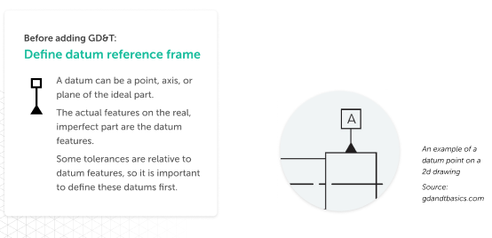
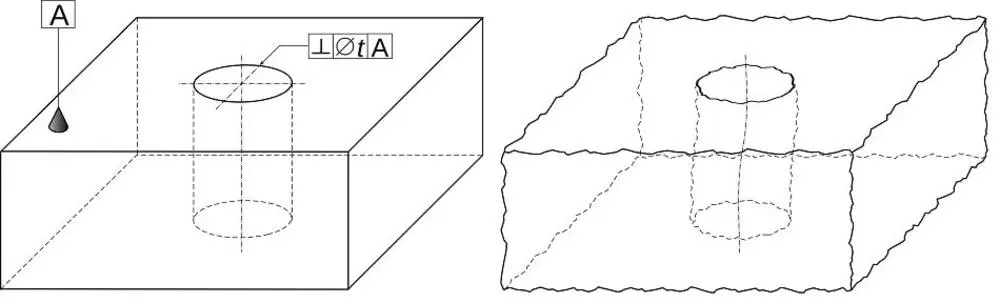
The Datum Reference Frame (DRF) forms the backbone of GD&T, representing the 3D coordinate system against which a part’s features are measured. It defines a part’s degrees of freedom, allowing precise positioning for inspection and assembly. Datums are theoretical points, lines, or planes, while datum features are the actual physical elements on a part.
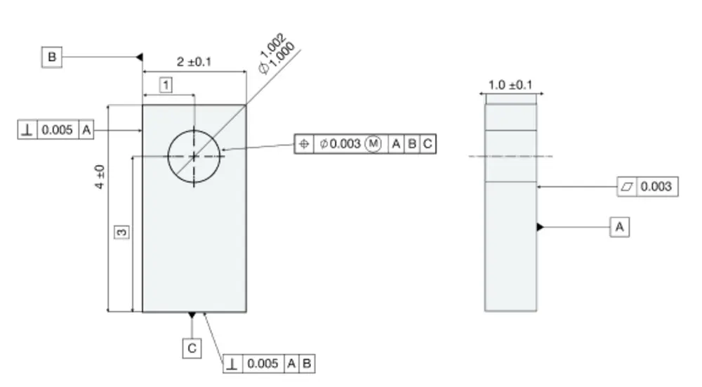
Basic dimensions are exact values used to describe the form, size, orientation, or location of a feature. These dimensions do not carry tolerances themselves but are controlled through GD&T’s feature control frames or notes.
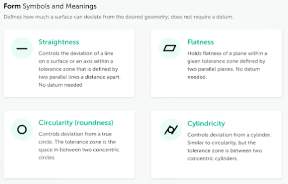
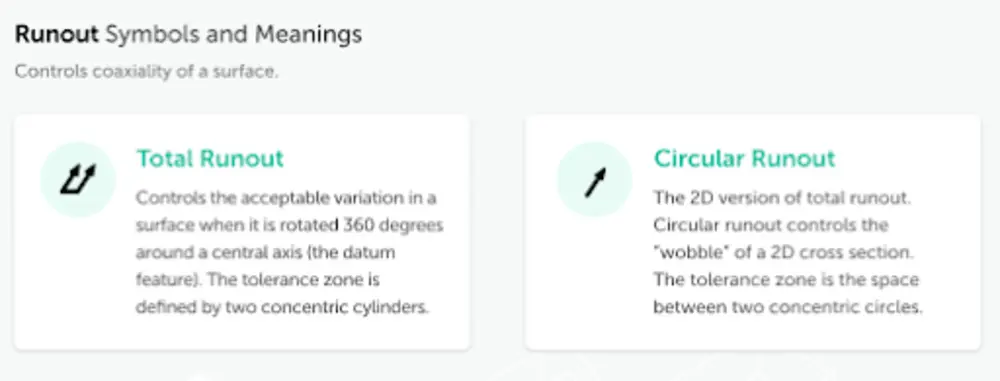
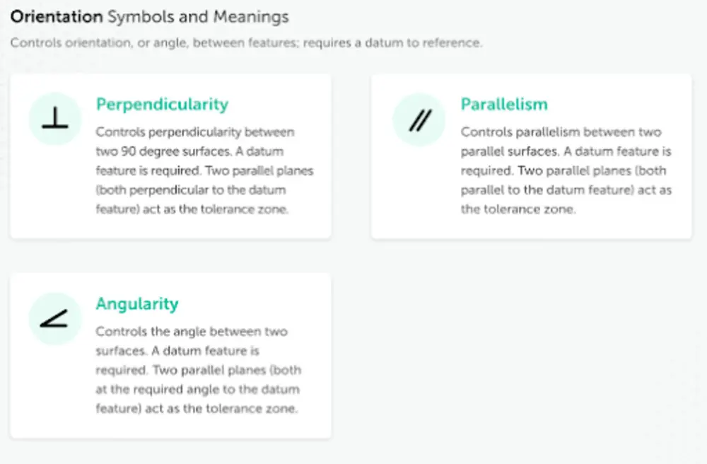
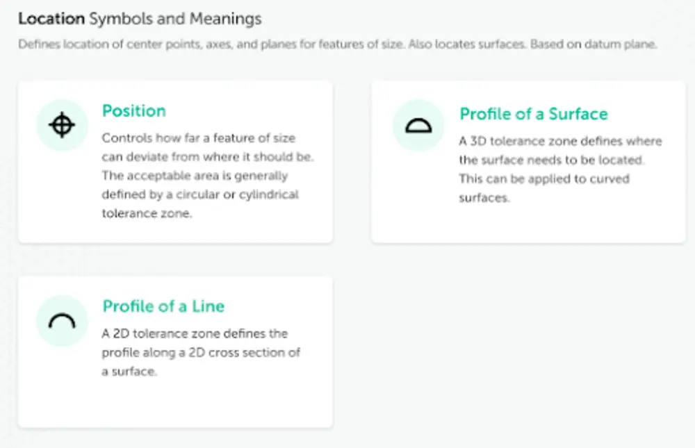
GD&T uses a set of standardized symbols to define geometric tolerances. These symbols represent characteristics like form, orientation, location, and runout. Each category controls specific aspects of a part’s geometry, such as its shape, tilt, or exact placement within an assembly.
Material condition modifiers such as Maximum Material Condition (MMC) and Least Material Condition (LMC) communicate tolerances based on a feature’s size. They allow for bonus tolerance when a feature deviates from its ideal size, providing flexibility in production without sacrificing quality.
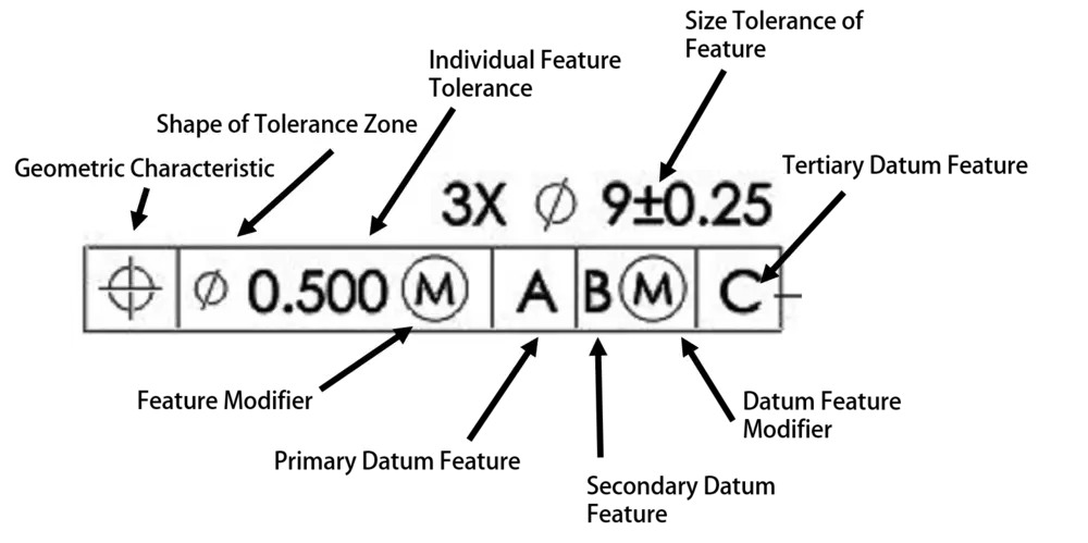
A feature control frame provides specific instructions for controlling a feature. It includes the type of geometric control, the allowable tolerance, and any necessary datum references. This ensures that each feature on a part meets the required tolerances for function and fit.
GD&T is an invaluable tool for ensuring that parts meet their intended function with precision and consistency. By providing a clear, standardized method of defining tolerances, GD&T simplifies the design-to-production process and reduces errors, ultimately saving time and cost. Understanding and applying GD&T will enhance communication between design and manufacturing teams, leading to better-quality products and smoother production workflows.
Explore more resources to deepen your knowledge of GD&T and learn how to implement these concepts effectively in your own projects. Start today by submitting well-defined drawings, getting instant quotes, and leveraging modern technology to streamline custom manufacturing.
Get the latest trends and facts about CNC fabrication from our blog.
Shenzhen Runkey Precision Technology Co. Ltd, a subsidiary of the Tensun Group, is your trusted one-stop solution for custom manufacturing from prototyping to production.Transforming your idea into reality with digital manufacturing resources,streamlined processes, expert guidance,accelerated timelines, and uncompromising quality.
©2024. CNC Fabrication All Rights Reserved.