- +8615586668226
- [email protected]
- No. 30, Hongbang Industrial Park, Shenzhen
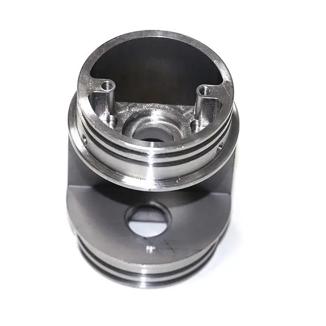
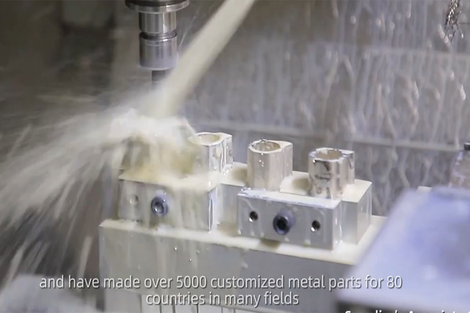
Tolerance in CNC machining refers to the permissible variation for a specific dimension of a machined part. It defines the acceptable range of deviation from the nominal dimension, usually represented as a plus or minus value. For instance, if a dimension is specified as 10 mm with a tolerance of ±0.1 mm, the actual dimension can range from 9.9 mm to 10.1 mm. As a representative of a CNC fabrication services manufacturing plant, I can attest to the critical role tolerance plays. It’s the backbone of precision in our industry.
Why does tolerance matter? Imagine assembling a complex machine like an aircraft engine. Every component must fit perfectly to ensure optimal performance and safety. Tight tolerances are crucial in such cases. If the parts don’t fit within the specified tolerance, the entire assembly can fail. This is why, at our CNC machining service plant, we emphasize the importance of machining with high precision. In my experience, tighter tolerances often translate to higher quality, but they also come with increased costs and production time. A tolerance of ±0.001″ is incredibly tight and requires specialized equipment and expertise. Striking the right balance between cost and quality is a key aspect of our job.
Standard machining tolerances are predefined tolerance values typically used when a dimension doesn’t have a specified tolerance. These standard tolerances are based on the International Organization for Standardization (ISO) standards, such as ISO 2768, and provide a general guideline for machining. Standard tolerance values are categorized into different classes, such as “fine,” “medium,” and “coarse,” based on the tolerance range and the dimension’s nominal size. When I first started in the industry, understanding these classifications was crucial.
The impact of standard machining tolerances on your projects can be significant. Using standard tolerance values can simplify the design process, as they provide a ready-made tolerance framework. However, relying solely on standard tolerances might not be suitable for all applications. For instance, if you’re designing a critical component for a medical device, you might need tighter tolerances than what the “fine” class under ISO 2768 offers. This requires deeper collaboration between engineers and CNC experts to achieve the right level of precision. At our plant, we often engage in detailed discussions with clients to understand their specific needs and guide them toward the most appropriate tolerance choices. Understanding the tolerance needs from the outset can save time and resources. The American Society of Mechanical Engineers provides useful guidelines in these situations.
In the world of CNC machining, understanding the different types of tolerances is fundamental. Tolerance defines the allowable variation in a dimension, and it can be expressed in three main ways: unilateral tolerance, bilateral tolerance, and limit tolerance. Each type serves a distinct purpose and impacts the design and manufacturing process differently.
Unilateral tolerance allows variation in only one direction from the nominal size. For example, if a dimension is specified as 10 mm with a unilateral tolerance of +0.1 mm, the actual dimension can range from 10 mm to 10.1 mm, but not below 10 mm. This type of tolerance is often used when a part needs to fit into a specific space or mate with another component in a particular way. We often recommend unilateral tolerance in designs where clearance or interference fits are critical.
Bilateral tolerances allow variation in both directions from the nominal size. A common example is a dimension specified as 10 mm ±0.1 mm. This means the actual dimension can range from 9.9 mm to 10.1 mm. Bilateral tolerance is versatile and commonly used in general CNC machining applications. They offer a balanced approach to dimensional control, making them a popular choice in many projects.
Limit tolerance specifies the upper and lower limits of a dimension directly. For instance, a limit tolerance might be expressed as 9.9 mm to 10.1 mm. This method clearly defines the allowable range without needing a nominal size and a plus/minus value. We often use limit tolerance in our CNC fabrication plant when the absolute limits are critical, and the nominal size is less important.
Choosing the right type of tolerance depends on the specific requirements of your project. Unilateral tolerances are ideal for ensuring a part fits in one specific direction, while bilateral tolerances offer a more balanced approach. Limit tolerances provide clear, direct limits that can be crucial for certain applications. It is important to be clear when you specify these.
Typical machining tolerances vary depending on the machining process used. For example, CNC milling typically achieves a standard tolerance of around ±0.1 mm (±0.004 inches). However, with specialized equipment and skilled operators, tighter tolerances down to ±0.025 mm (±0.001 inches) or even better can be achieved. When customers approach us with requirements for high precision, we often suggest precision machining techniques combined with processes like grinding or lapping to meet those needs.
CNC turning, on the other hand, generally offers slightly tighter tolerances compared to milling. A standard tolerance for CNC turning is around ±0.05 mm (±0.002 inches), and with extra care, tolerances as tight as ±0.01 mm (±0.0004 inches) are achievable. In our machine shop, we’ve successfully delivered parts with even tighter tolerances for specialized applications, such as in the aerospace industry. It’s important to remember that achieving these tight tolerances often requires multiple passes, specialized cutting tools, and careful monitoring of the machining process.
Other machining methods, such as drilling or boring, have their own typical tolerance ranges. Drilling usually has a wider tolerance, around ±0.2 mm (±0.008 inches), while boring can achieve tolerances similar to CNC turning. Grinding is a process known for its precision, often used to achieve very tight tolerances, in the range of ±0.005 mm (±0.0002 inches) or better. Each machining method has its strengths and limitations when it comes to tolerance, and understanding these nuances is crucial for selecting the right process for your project. It is important to know the tolerance band that you need. Materials and machining go hand in hand for these projects.
Specifying tolerances accurately is crucial for ensuring that your CNC machined parts meet the required specifications. The first step is to identify the critical dimensions and features of your part. Consider which dimensions directly affect the part’s functionality, fit, and assembly with other components. Once you’ve identified these critical dimensions, you can start assigning appropriate tolerances. A good starting point is to consider standard machining tolerances based on ISO standards like ISO 2768. However, always evaluate whether these standard tolerances are sufficient for your specific application.
When specifying tolerances, use clear and unambiguous notation. For bilateral tolerances, use the ± symbol followed by the tolerance value. For example, 20 mm ±0.1 mm indicates that the dimension can vary from 19.9 mm to 20.1 mm. For unilateral tolerances, specify the direction of the allowable variation, such as 20 mm +0.1 mm/-0 mm. This means the dimension can range from 20 mm to 20.1 mm but cannot be smaller than 20 mm. Limit tolerances are specified by providing the maximum and minimum allowable dimensions, for example, 19.9 mm – 20.1 mm.
It’s also essential to consider the tolerance stack-up in assemblies. Tolerance stack-up refers to the cumulative effect of tolerances when multiple parts are assembled. Each part’s tolerance contributes to the overall variation in the assembly. To minimize tolerance stack-up issues, carefully analyze how the tolerances of individual parts interact and affect the final assembly dimensions. In our CNC fabrication plant, we often use advanced simulation tools to predict and manage tolerance stack-up, ensuring that the final product meets the required specifications. When you are dealing with multiple part tolerances it is easy for errors to occur.
Geometric Dimensioning and Tolerancing (GD&T) is a symbolic language used to define a part’s geometry and its allowable variation. It goes beyond basic dimensional tolerances by specifying the geometric characteristics of features, such as form, orientation, location, and runout. GD&T uses a set of standardized symbols and rules defined by the American Society of Mechanical Engineers (ASME) Y14.5 standard or ISO equivalents.
GD&T plays a crucial role in modern CNC machining by providing a more comprehensive and precise way to define a part’s requirements. For example, GD&T can specify the true position of a hole, which not only controls its location but also its perpendicularity to a surface. This level of control is often necessary for parts that need to interface precisely with other components. In my experience, GD&T helps to have better communication between design and manufacturing.
One of the key benefits of GD&T is that it defines the function and relationship of features, rather than just their size and location. For instance, profile tolerances can control the shape of a complex surface, ensuring that it fits correctly with a mating part. GD&T tolerances can be more complex to learn, but they offer much greater control over the final part. At our CNC fabrication plant, we’ve found that using GD&T reduces ambiguity and misinterpretation, leading to fewer errors and higher-quality parts. GD&T is particularly useful for complex parts with tight tolerance requirements, such as those used in aerospace, medical devices, and other high-precision applications.
Achieving tight tolerance in CNC machining requires a combination of factors, including the right equipment, skilled operators, and a well-defined process. Tight tolerances refer to very small allowable variations, often in the range of ±0.01 mm (±0.0004 inches) or even tighter. One of the first considerations is the CNC machine itself. High-precision machines with advanced features like linear motors, high-resolution encoders, and thermal stabilization are essential for achieving tight tolerances. Regular maintenance and calibration of these machines are also critical.
Another crucial factor is the choice of cutting tools. High-quality, sharp cutting tools designed for specific materials and operations can significantly impact the achievable tolerance. Tool wear must be monitored closely, as worn tools can lead to dimensional inaccuracies. In our machine shop, we use advanced tool management systems to track tool life and ensure that tools are replaced or sharpened before they affect part quality. CNC screw machining also plays a role here.
The machining process itself also plays a vital role. Techniques like using multiple finishing passes, optimizing cutting parameters (speed, feed, depth of cut), and employing advanced strategies like high-speed machining or trochoidal milling can help achieve tighter tolerances. Additionally, using specialized techniques like grinding, lapping, or honing as secondary processes can further refine dimensions and achieve extremely tight tolerances. It’s also important to consider the material being machined, as some materials are more challenging to machine to tight tolerances than others. This is where working with experienced machinists can make a big difference.
International standards for machining tolerances provide a common framework for specifying and interpreting tolerances globally. The most widely recognized standards are those published by the International Organization for Standardization (ISO). ISO 2768 is a commonly used standard that defines general tolerances for linear and angular dimensions. It specifies four tolerance classes: f (fine), m (medium), c (coarse), and v (very coarse). Each class defines a tolerance range based on the nominal size of the dimension. These types of standardized tolerances make understanding requirements much simpler.
Another important ISO standard is ISO 286, which defines a system of limits and fits. It specifies tolerance grades (IT grades) that define the tolerance range for holes and shafts. IT grades range from IT01 to IT18, with lower numbers indicating tighter tolerances. For example, IT6 is a common tolerance grade for precision fits, while IT11 might be used for looser clearance fits. These engineering tolerances are essential for anyone in the machining industry.
In addition to ISO standards, some industries use standards published by other organizations. For instance, the aerospace industry often uses standards developed by SAE International. These standards often build upon ISO standards but may include additional requirements or stricter tolerances specific to aerospace applications. When working with international clients, we often encounter various standards. Being familiar with these different standards helps ensure that we meet all specified requirements. Understanding and adhering to these international standards is essential for ensuring consistency, quality, and interoperability in CNC machining across different countries and industries.
The choice of material significantly impacts the achievable tolerance in CNC machining. Different materials have varying properties, such as hardness, thermal expansion, and machinability, which can affect dimensional stability and the precision of the machining process. For example, softer materials like aluminum and brass are generally easier to machine and can achieve tighter tolerances compared to harder materials like stainless steel or titanium. This is something we always discuss with clients during the material selection phase.
Harder materials often require more robust cutting tools, slower cutting speeds, and more frequent tool changes, which can impact the achievable tolerance. Additionally, some materials are more prone to thermal expansion or contraction during machining, which can affect dimensional accuracy. In our CNC fabrication plant, we work with a wide range of materials and have developed specific strategies for each to ensure optimal tolerance control. For instance, when machining stainless steel, we often use specialized coolant systems to manage heat and maintain dimensional stability. We also consider plating and finishes in this stage.
The machining method itself also influences the achievable tolerance. As mentioned earlier, processes like CNC milling and CNC turning have different typical tolerance ranges. Precision machining techniques, such as grinding or honing, can achieve much tighter tolerances compared to conventional machining methods. The choice of machining method depends on the specific tolerance requirements, the complexity of the part, and the material being machined. We often combine different machining methods to achieve the desired results. For example, we might start with CNC milling to remove most of the material and then use grinding to achieve the final dimensions and tight tolerances.
Determining tolerances is a critical aspect of the design process that requires careful consideration of various factors. One of the first steps is to understand the function of the part and how it interacts with other components in an assembly. This will help identify the critical dimensions that require tight tolerances and those that can have looser tolerances. It’s also essential to consider the manufacturing process that will be used to produce the part. Different machining methods have varying capabilities when it comes to achieving tolerances, so it’s crucial to choose a process that can meet the required precision.
Another best practice is to use standard tolerances whenever possible. Standards like ISO 2768 provide a good starting point for assigning tolerances to non-critical dimensions. This can simplify the design process and reduce the risk of errors. However, always evaluate whether these standard tolerances are sufficient for your specific application. For critical dimensions, it’s often necessary to perform a detailed tolerance analysis, considering factors like tolerance stack-up, material properties, and environmental conditions.
Collaboration between designers, engineers, and machinists is also crucial for determining tolerances. Designers should consult with experienced machinists to understand the capabilities and limitations of the machining process. This can help avoid specifying tolerances that are unnecessarily tight or difficult to achieve, which can increase costs and lead times. In our CNC fabrication plant, we encourage early collaboration between our clients’ design teams and our machining experts. This collaborative approach helps ensure that the specified tolerances are realistic, achievable, and cost-effective. Finding the right tolerance for each project is essential.
Here is a simple table to illustrate some key points:
| Aspect | Description |
| Tolerance | Permissible variation in dimension. Essential for part functionality and assembly. |
| Standard Tolerance | Predefined values (e.g., ISO 2768) simplify design but may not suit all applications. |
| Tight Tolerance | Very small allowable variations, often ±0.01 mm or better. Requires specialized equipment and processes. |
| GD&T | Geometric Dimensioning and Tolerancing. Provides comprehensive control over part geometry beyond basic dimensional tolerances. |
| Material Impact | Material properties affect achievable tolerance. Softer materials generally allow for tighter tolerances than harder ones. |
| Process Impact | Different machining methods have varying tolerance capabilities. Precision techniques like grinding offer the tightest tolerances. |
What is the difference between unilateral and bilateral tolerance?
Unilateral tolerance allows variation in only one direction from the nominal size, while bilateral tolerance allows variation in both directions. For example, a unilateral tolerance might be 10 mm +0.1 mm/-0 mm, while a bilateral tolerance would be 10 mm ±0.1 mm. Choosing between them depends on how a part needs to fit or function within an assembly.
How tight of a tolerance can CNC machining achieve?
CNC machining can achieve very tight tolerances, often down to ±0.01 mm (±0.0004 inches) or even better with specialized equipment and processes. High-precision machines, specialized cutting tools, and techniques like grinding or honing can further refine dimensions to achieve extremely tight tolerances, sometimes in the range of ±0.005 mm (±0.0002 inches) or less.
What is a standard tolerance in CNC machining?
A standard tolerance in CNC machining refers to predefined tolerance values that are commonly used when a dimension doesn’t have a specified tolerance. These standard tolerances are often based on international standards like ISO 2768, which defines general tolerances for linear and angular dimensions. They are categorized into different classes like “fine,” “medium,” and “coarse,” providing a general guideline for machining. Using standard machining tolerances can greatly simplify the process.
How does material choice affect machining tolerance?
Material choice significantly impacts achievable tolerance. Softer materials like aluminum and brass are generally easier to machine and can achieve tighter tolerances compared to harder materials like stainless steel or titanium. Material properties such as hardness, thermal expansion, and machinability all play a role in determining how precisely a part can be machined.
What is GD&T, and why is it important?
Geometric Dimensioning and Tolerancing (GD&T) is a system for defining and communicating engineering tolerances. It uses a symbolic language to specify the allowable variation in part geometry, including form, orientation, location, and runout. GD&T is important because it provides a more comprehensive and precise way to define a part’s requirements compared to using only basic dimensional tolerances. It helps ensure that parts fit and function correctly in an assembly, especially for complex components with tight tolerance requirements. GD&T also helps reduce ambiguity and misinterpretation between design and manufacturing.
How can I ensure my CNC machined parts meet the specified tolerances?
To ensure your CNC machined parts meet the specified tolerances, it’s essential to work with an experienced CNC machining service provider that has the right equipment, skilled operators, and a robust quality control process. Clearly communicate your tolerance requirements, use appropriate tolerance notations, and consider using GD&T for critical dimensions. Regular communication between your design team and the machining experts can also help ensure that everyone understands the requirements and that the parts are produced to the correct specifications.
Tolerance is the permissible variation in a dimension and is crucial for part functionality and assembly.
Standard machining tolerances, based on standards like ISO 2768, provide a general guideline but may need adjustment for specific applications.
Unilateral, bilateral, and limit tolerances offer different ways to specify allowable variation, each with its own use cases.
Tight tolerances require specialized equipment, cutting tools, and machining processes.
GD&T provides a comprehensive way to define part geometry and tolerances, going beyond basic dimensional tolerances.
Material choice and machining method significantly influence achievable tolerance.
Collaboration between designers and machinists is essential for determining realistic and cost-effective tolerances.
Adhering to international standards for machining tolerances ensures consistency and quality in global manufacturing.
As an experienced professional in the CNC fabrication industry, I’ve seen firsthand how crucial understanding machining tolerances is for producing high-quality parts. Whether you’re designing a simple bracket or a complex aerospace component, paying attention to tolerances can make the difference between success and failure. I hope this comprehensive guide has provided you with valuable insights into the world of CNC machining tolerances. Remember, precision is not just about hitting the numbers; it’s about ensuring that every part fits perfectly, functions flawlessly, and contributes to the overall success of your project. If you have a project requiring On Demand Manufacturing, contact us today, we are experts in CNC Machining and will be able to assist you with your needs. Our Fabrication Services are second to none, utilizing Sheet Metal Fabrication and Aluminum Extrusion. Our expertise extends to Surface Finishing, ensuring every project meets the highest standards of quality and precision.


Get the latest trends and facts about CNC fabrication from our blog.
Shenzhen Runkey Precision Technology Co. Ltd, a subsidiary of the Tensun Group, is your trusted one-stop solution for custom manufacturing from prototyping to production.Transforming your idea into reality with digital manufacturing resources,streamlined processes, expert guidance,accelerated timelines, and uncompromising quality.
©2024. CNC Fabrication All Rights Reserved.